R E S H A P
E P A T H S
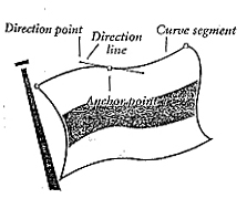
What is a Bezier curve?
In Illustrator, a curve segment
is also called a Bezier curve. A Bezier curve consists of two anchor points
connected by a curve segment, with at least one direction line attached to each
anchor point. If an anchor point connects a curve and a straight-line segment,
it will have one common direction line. If an anchor point connects two curve
segments, it will have a pair of direction lines.
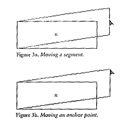
If you move an anchor point,
segments connected to it will reshape. If you move a curve segment, connecting
anchor points will not move along with it. If you move a line segment,
connecting anchor points will also move.
|
To move an
anchor point or a segment:
- Choose
the direct selection tool.
- Press
and drag the anchor point or segment.
- Hold
down the shift to constrain the movement of an anchor point to 45, 90,
135, or 180 degrees.
- If
all the anchor points on the path are selected, you will not be able
to move an individual point or segment. Deselect the object, then
reselect an individual point.
- Hold
down the shift and click to select more than one anchor point at a
time.
|
 |
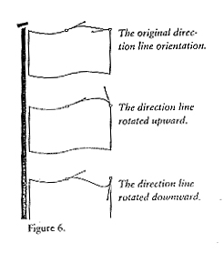
A more precise way to reshape a
curve is to lengthen, shorten, or change the angle of its direction lines.
|
To reshape a curve
segment:
- Choose
the direct selection tool.
- Click
on an anchor point.
- Press
and drag a direction point (the end of the direction line) toward or away
from the anchor point. –or- Rotate the direction point around the anchor
point. The anchor point will remain selected when you release the mouse
|
 |
|
To convert a corner anchor
point into a curve anchor point:
- Choose
the direct selection tool
- Click
on the edge of the object. The anchor points will be hollow.
- Choose
the convert-direction-point tool (it’s under the pen tool), or hold down
control with any selection tool.
- Press
on an anchor point, and then drag away from it. Direction lines will be
created as you drag. The further you drag, the rounder the curve will
become.
- To
further modify the curve, choose the direct selection tool, then drag the
anchor point or a direction line.
- Direction
lines on a smooth curve form a straight line in relationship to each other
even if one direction line is moved, or the curve segment or anchor point
they are connected to is moved.
- If
the new curve segment twists around the anchor point as you drag, keep the
mouse button down, rotate the direction line back around the anchor point to
undo the twist, then continue to drag in the new direction.
|
 |
To convert a curve anchor
point to a corner anchor point:
- Choose
the direct selection tool.
- Click
on the edge of the object to display its anchor points.
- Choose
the convert-direction-point tool (or hold down control).
- Click
on the curve anchor point. Don’t drag! Its direction lines will be
deleted.
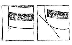
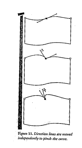
The direction lines in a
pinched curve rotate independently of each other, they don’t stay in a
straight line.
|
To pinch a curve
inward:
- Choose
the direct selection tool.
- Click
on the edge of an object to display its anchor points.
- Choose
the convert-direction-point tool (or hold down control).
- Press
and drag a direction point at the end of one of the direction lines. The
curve segment will reshape as you drag.
- Choose
the direct selection tool. Click on an anchor point.
- Drag
the other direction line for that anchor point.
- To
revert an independent-rotating direction line pair back to its previous
straight line alignment and produce a smooth, unpinched curve segment,
choose the convert-direction-point tool, then click on either direction
point.
|
 |
|
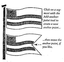
To add anchor points to a
path manually:
- Choose
the add-anchor-point tool.
- Click
on the edge of the object. A new, selected anchor point will appear. Repeat,
if desired, to add more points.
- If
you don’t click precisely on a segment of an object, a warning prompt will
appear. Click “OK” and try again.
- Hold
down control to use the add-anchor-point tool when the pen tool is selected
and is over a segment.
|
 |
The Add Anchor Points Filter
inserts one anchor point midway between every two existing anchor points.
To add anchor points to a
path using a filter:
- Select
an object, or objects.
- Choose
Filter>Objects>Add Anchor Points
|
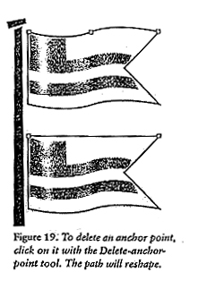
To delete anchor points from
a path:
- Select
an object.
- Choose
the delete-anchor-point tool.
- Click
on an anchor point. The point will be deleted and an adjacent point will
become selected. Repeat to delete other anchor points if desired.
- If
you do not click precisely on an anchor point, a warning prompt will appear.
Click “OK” and try again.
|
 |
An open path can be split into
two paths and a closed path can be opened using the scissors tool. A path can be
split at the anchor point or in the middle of a segment.
|
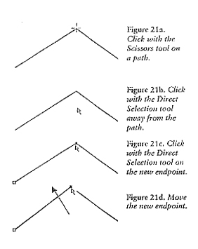
To split a path:
- Choose
any selection tool.
- Click
on an object to display its anchor points.
- Choose
the scissors tool.
- Click
on the object’s path. If you click on a closed path, it will turn into a
single, open path. If you click on an open path, it will be split into two
paths. If you click on a segment, two new end points will appear, one on top
of the other. If you click on an anchor point, a new anchor point will
appear on top of the existing one. The new end points will be selected and
will overlap each other.
To move
the new end points apart:
- Choose
the direct selection tool.
- Click
away from the object to deselect it.
- Click
on the object’s path.
- Click
on the new endpoint, then drag away to reveal the endpoint underneath.
- You
cannot split an open path if it has text on it or inside it.
|
 |
The average command reshapes
one or more paths by precisely realigning their end points or anchor points to
the horizontal and/or vertical axis.
|
To average anchor
points:
- Choose
the direct selection tool Hold down Shift and click on two or more anchor
points. You might want to zoom in on the objects so you can clearly see the
selected points.
- Choose
Object>Path>Average.
- Click
“Both” to overlap the points along both the horizontal and vertical
axes. Choose this option if you want to join them later into one point.
-or-
- Click
“Horizontal” to align the paths along the horizontal axis.
-or-
- Click
“Vertical” to align the points along the vertical axis.
- Click
“OK” or press return.
|
 |
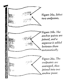
If you align two end points on
top of each other and then execute the Join command, they will combine into one
anchor point. If the end points are not on top of each other, a new
straight-line segment will be created between them. The Join command will not
add direction lines to the new anchor point.
|
To join two endpoints:
- Choose
the direct selection tool.
- If
you want to combine two endpoints into one, move one endpoint on top of the
other manually, or use the Average command (Axis:Both) to align them.
- Hold
down Shift and click on two endpoints or marquee them.
- Choose
Object>Path>Join. If the end points are not on top of each other, the
Join command will connect them with a straight-line segment. If the
endpoints are aligned on top of each other, the Join dialog box will open.
In
the Join dialog box:
- Click
Corner to join corner points into one corner point with no direction lines,
or to convert two curve points (or a corner point and a curve point) into
one curve point with independent-moving direction lines. This is the default
setting.
-or-
- Click
smooth to connect two curve points into a curve point with direction lines
that move in tandem.
- Click
“OK” or press return.
- To
average and join two selected endpoints via one keystroke, hold down Shift,
Control, & Alt (Command+Option /MAC) and press “J.”
|
 |
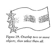
The filters on the Pathfinder
palette combine multiple objects into one new object. The Combine filter is used
in these instructions.
|
To combine two objects into
one using Pathfinder filters:
- Position
two or more objects so they overlap.
- Choose
the selection tool
- Press
and drag a marquee around (or at least touching) all the objects.
- If
the Pathfinder palette is not on the screen, click Window>Show
Pathfinder.
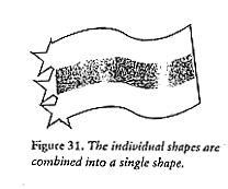
- In
the Pathfinder palette, click the “Combine” icon. The individual objects
will combine into one closed object and will be colored with the top
object’s paint attributes.
|
 |
Go
to the PEN TOOL handout
Return to the Illusory Line
Assignment Sheet
Return to
Greatest Hits
Return to Home
Page